





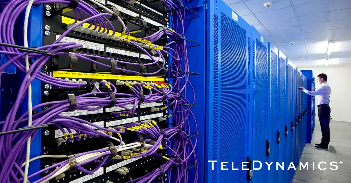
Discussions about data centers usually focus on servers, switches, storage, virtualization, and cybersecurity. An aspect that is often overlooked is cabling. Data center cabling directly affects performance, uptime, troubleshooting, scalability, and even cooling, all of which are vital to long-term operational efficiency.
In this article, we take a closer look at this critical aspect of data centers, examine the most common cable types and design approaches, and briefly explore how AI data centers, in particular, are changing cable requirements.
Why cabling matters so much
Cabling is often thought of as a passive utility that really doesn’t do anything other than transfer data. In fact, it should be treated as a fundamental part of data center architecture whose design directly affects data center performance.
Poor cabling can cause outages and overheating and can be an obstacle to expansion, while good cabling ensures reliability, scalability, cost-effective maintainability, and sufficient airflow. A well-designed data center cabling system should not only support today’s speeds and applications, but also provide a flexible foundation for tomorrow’s requirements.
Data center cabling categories
There are various types of cabling used in data centers. Each one has different characteristics and use cases. The two main categories, as they are for all networking cabling, are copper and fiber optics.
Copper cabling
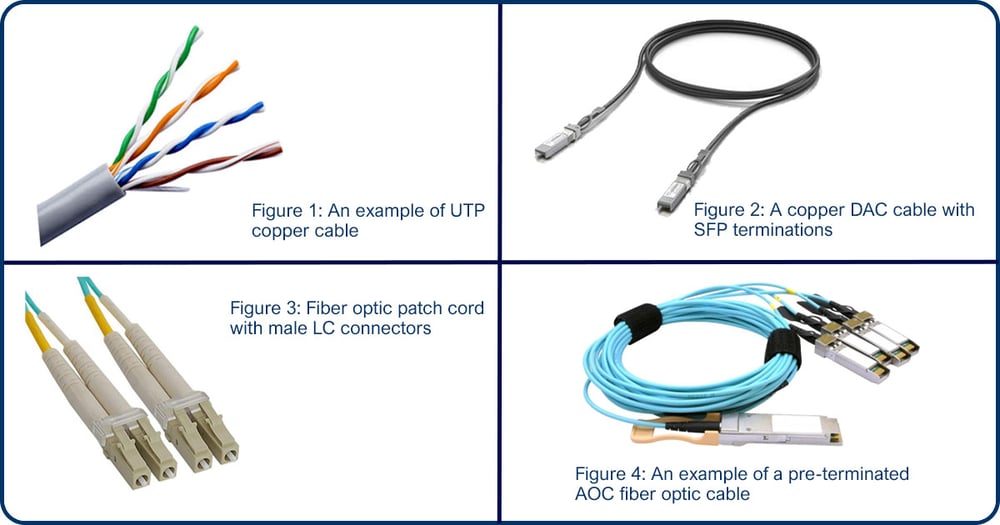
Data center copper cabling comes in various types. First, there are more conventional unshielded twisted pair (UTP) copper cabling with RJ-45 connectors, often informally called Ethernet cables (see Figure 1). For data centers, this is usually Cat 6A or better, which can support speeds of up to 10 Gbps over lengths of up to 100 meters. It is cheap, widely available, and can easily connect to switches, servers, and other network devices. It is generally simple to install and terminate.
Direct Attach Copper, or DAC, is another type of copper cabling common in server-to-switch connections (see Figure 2). It is essentially a copper cable with integrated SFP-type transceivers on either end that can plug into SFP- and QSFP-type interfaces. The transceivers on DACs may be active (receive power from the switch) or passive, depending on distance and speed requirements. They are commonly used for short, high-speed links within the same rack or between nearby racks, offering low cost, low power consumption, and low latency compared with optical alternatives. They are cheaper than fiber cables but bulkier, and their speeds and compatibility are highly platform-dependent.
Fiber optic cabling
Fiber optic cabling comes in two fundamental types, single-mode and multimode, which describe the actual structure and properties of the fiber optic strand itself. Single-mode fiber can support better performance in terms of both speed and distance, but its manufacturing and related electronics are somewhat more expensive.
In conventional data centers, multimode fiber is still widely used for short-distance connections within the facility. However, single-mode fiber is increasingly preferred for new deployments, high-speed backbones, data center interconnects, and environments that need a longer upgrade path toward speeds like 100G, 400G, 800G, and beyond.
For both types, various connectors are used to terminate the fibers at either end. Which one is chosen depends on the optical transceiver, fiber type, cabling density, polarity requirements, and the structured cabling design being used.
Fiber optic cables also have a counterpart to copper’s DAC cables: Active Optical Cables, or AOCs (see Figure 4). These are fiber optic cables pre-terminated to transceiver-type assemblies that plug directly into an SFP/QSFP-type port. Using them is simpler than purchasing a fiber optic patch cord and transceiver separately, but an AOC can be less flexible than structured cabling fiber optics, which we will discuss shortly. Keep in mind that AOCs may sometimes be incorrectly referred to as DACs by marketing teams or in manufacturer documentation. These are distinctly different due to the medium used.
Medium and cable type comparison table
The following table compares media and cable types for use in data centers and outlines their strengths, limitations, and typical use cases.
Structured cabling
Structured cabling is a method of cable installation that simplifies network deployments, modifications, and long-term management. Often used to interconnect end users to the network by using network jacks permanently connected to patch panels in telecom closets, it is also widely used within data centers as well.
Structured cabling in a data center requires proper planning for the placement of copper patch panels and fiber termination cassettes. Depending on the broader data center architecture, which we will touch on shortly, these cable termination points should be determined in advance and installed accordingly. The deployment of structured cabling is usually done for the long term because it is difficult to modify, so proper planning is vital for longevity, scalability, and sustainability.
ANSI/TIA-942 is one of the key standards used for data center infrastructure. It defines requirements for data center physical infrastructure, including telecommunications, electrical, mechanical, architectural, security, fire safety, and site-related considerations.
In comparison, point-to-point cabling (i.e., connecting a server directly to a switch without any intermediate structured cabling infrastructure) may be fast to deploy initially, but it becomes difficult to maintain as the data center grows. Structured cabling requires more planning and discipline, but improves scalability, documentation, and operational control.
Data center cabling architectures
The types of cables used and the design of structured cabling are both affected by the data center design. There are two primary approaches, which define the location of the network device, typically a switch, to which servers will connect. As we will see, each approach has its own pros and cons.
Top of rack (ToR)
The term “top of rack” essentially indicates that there is a network switch at the top of each individual rack where servers and services are hosted. Cabling runs from the servers, or from the hardware on which virtual servers are hosted, to the ToR switch. This switch, in turn, is connected to uplinks to the data center backbone network, typically organized around a spine-and-leaf architecture (discussed below).
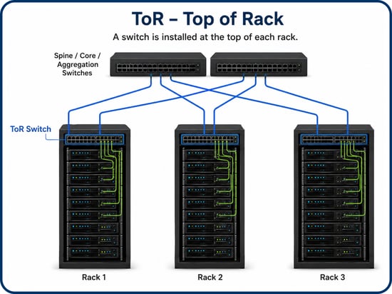
A ToR arrangement can theoretically use point-to-point cabling between the servers and the switch but can also benefit from structured cabling within the same rack. Connections between ToR switches and the data center backbone network are typically made via structured cabling between racks.
End/middle of row (EoR/MoR)
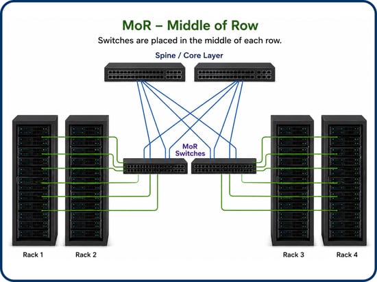
End-of-row and middle-of-row approaches follow the same idea as the ToR but use a single switch serving multiple racks. The EoR solution has a single large switch at the end of a rack row that serves all servers in that row. The MoR solution places the switch somewhere in the middle of the row, with several MoR switches deployed per row, serving the racks closest to them.
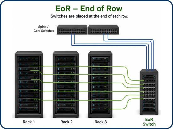
Both approaches require a higher degree of planning for structured cabling and the types of switches deployed than ToR. The location where the EoR or MoR switches are placed must also be equipped with the appropriate structured cabling termination to accommodate this architecture. However, in the long run, these arrangements can be more efficient and cost-effective.
Spine/leaf architecture
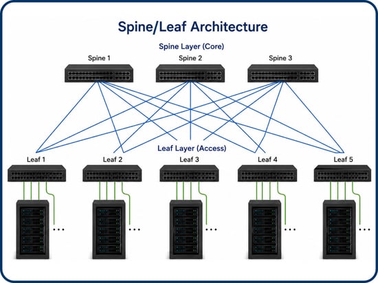
In all of the above cases, the typical backbone architecture of a data center is a spine/leaf approach. This architecture is a two-tier data center network design where every leaf switch connects to every spine switch in a full mesh. Such a design is more efficient and fault-tolerant than a traditional hierarchical design but relies on appropriate cabling. Indeed, when the ToR, EoR, or MoR switches serve as leaves in such a design, more connections to the spines are required, making proper cabling even more important.
Rack architecture comparison table
The following table compares the architectures typically used for data centers, and the impact they have on cabling.
Cabling and data center performance
Cabling can have a profound effect on data center performance in multiple areas:
- Supported throughput can be impacted since different cable types support different capacities, which must be taken into account.
- Link stability, signal loss, and attenuation are all phenomena that can be observed on cabling of all types and must be monitored appropriately.
- Latency can directly affect certain applications, and particular cables can contribute to this, affecting delay-sensitive workloads.
- Transceiver and media compatibility is an issue, especially with cables that require separate transceivers or have built-in transceivers on either end.
Among the most unintuitive ways that cabling can affect data center performance is its impact on cooling and airflow. Bundles of cables can be bulky and obstruct airflow. Large cable bundles behind servers can restrict hot-air exhaust, and overhead cabling may also obstruct natural airflow that cools racks and equipment. Good cabling must include good thermal design. Clean cable routing helps maintain predictable airflow, reduces cooling inefficiency, and lowers the risk of hot spots.
Labeling, documentation, and operations
A data center can have anywhere from several hundred to potentially hundreds of thousands of individual cables. Every cable should have a unique identifier, with both ends of each cable labeled. Documentation should be maintained that indicates source, destination, cable type, port rack, patch panel, speed, and the purpose of each cable. Such documentation helps reduce downtime by significantly speeding up the troubleshooting of physical-layer cabling issues.
Specialized tools for this purpose have been developed, but remember that even maintaining a disciplined spreadsheet is vastly preferable to undocumented cabling!
Related reading: Data center and telecom closet cabling best practices
Power cabling considerations
One type of cabling we didn’t talk about is power cabling. Even though it is often discussed separately from network cabling, it is important to consider. Servers, switches, storage systems, and other critical equipment should be connected via well-organized power paths, typically with dual power supplies connected to separate A and B power feeds. This provides power redundancy and helps maintain service availability if one power path fails. Power cables should also be routed carefully, kept separate from data cabling where appropriate, clearly labeled, and managed to prevent accidental disconnection or airflow obstruction behind the racks.
What changes for AI data centers?
A while back, we did a piece on AI data centers, and how their design and operation are fundamentally different from traditional data centers due to the nature of their workloads. We approached the differences in general terms, but how do these differences affect cabling?
In traditional enterprise data centers, traffic flows among end users, applications, storage, and the Internet. In AI data centers, enormous volumes of traffic flow among GPUs, servers, and storage systems, which means traffic volume increases dramatically, but it remains largely within the same data center and, in many cases, within the same row or rack. This means that AI workloads require very high bandwidth, very low latency, and highly predictable data transfer performance. This need often increases the use of high-speed fiber optic cabling, especially single-mode fiber in larger or more scalable designs. However, DACs, AOCs, and multimode fiber may still be used for shorter links depending on the architecture.
Overall, AI environments are even more demanding than traditional data center deployments when it comes to cabling and require careful planning that accounts for power, cooling, and network architecture.
Conclusion
Data center cabling is easy to underestimate and dismiss because it sits below the visible layers of compute, storage, networking, and applications. But when designed properly, it becomes a long-term asset that supports uptime, performance, resilience, operational efficiency, and future growth.
You may also like:
How to prepare your network for the demands of AI
Structured cabling: best practices for future-ready connectivity
Copper cabling categories explained: which cable should you choose?



Comments