


Over the past few weeks we’ve looked at different ways to structure multisite VoIP deployments. The truth is, each business is unique and sometimes a customized architecture is needed. In this article we look at a hybrid solution. A hybrid call processing deployment allows you to craft a solution that is perfectly tailored to a specific customer’s needs.
Business needs are paramount
When designing any network solution, it is important to successfully translate the needs of the business into a viable telephony network design. The network architecture should be a direct outcome of the business needs at each location.
Case study
Let’s use a hypothetical customer case to illustrate how this works.
A company called YourEnterprise.com requires a multisite telephony deployment. The company is headquartered in Houston, Texas and has several branch offices as shown in the diagram below. The telephones in all the branches and at HQ are configured to use four-digit short codes to communicate with each other over the WAN.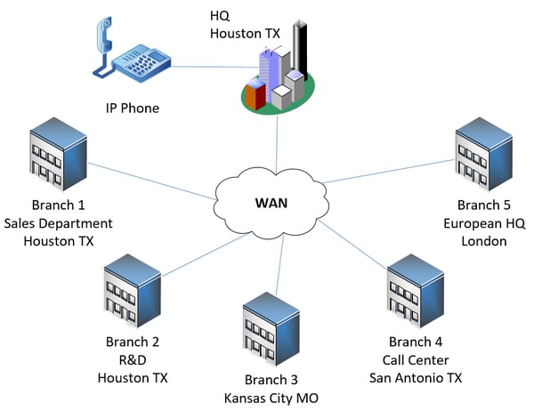
Business requirements per site
Headquarters (HQ) is equipped with a PSTN connection capable of providing connectivity for all of the phones, both remote and local. It also has an IP PBX that provides centralized call control facilities to all local and remote telephony devices. HQ is connected to its branch offices via a private WAN that carries both voice and data traffic between company locations.
Branch 1 is also located in Houston, about five miles away from the headquarters building. This facility is used by sales reps who are often out of the office. The reps mostly use mobile phones, and only use their desk phones for the relatively short amount of time they spend in the office.
Branch 2 is an R&D facility in Houston, where employees are at their desks or in the lab for most of their work days. Telephony is an important tool for the management team there, although rare interruptions in service for no more than several minutes are tolerable. Employees working in the labs, however, do not consider telephony mission critical.
Branch 3 is located in Kansas City and provides a local contact point for customers in Missouri. Employees here have daily interaction with local clients over the phone.
Branch 4 is located in San Antonio. It houses the company’s call center.
Branch 5 is the company’s European headquarters located in London.
Providing a hybrid solution on a branch-by-branch basis
Branch 1
Telephony for employees at Branch 1 is not mission critical, since the bulk of their calls are made from cell phones. Therefore, centralized call control and PSTN connectivity can be implemented without the need for any backup or redundancy built into the implementation. Additionally, Branch 1 is in the same area code as HQ, so centralized PSTN connectivity would not create issues related to caller ID or long-distance charges (for more information about potential issues arising from centralized PSTN connectivity, click here). The result is a design as shown in the diagram below.
This implementation does not involve a local IP PBX or voice gateway at Branch 1, thus saving on cost, maintenance, and hosting of equipment. If the WAN fails, telephony service will also fail.
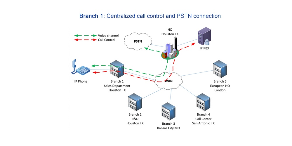
Branch 1 summary:
- Centralized call control and PSTN connectivity without redundancy or backup
- If the WAN fails, telephony service will also fail
Branch 2
Telephony at this branch is only mission critical for the management of the R&D facility. Since only a subset of users require redundancy, the site can function with centralized call control and PSTN connectivity under normal circumstances, but needs redundancy for certain critical users. Since we are still in the same area code as HQ, once again, caller ID and long-distance charges are not an issue. The following diagram shows call control and voice communication under normal circumstances (left) and in the event of a WAN failure (right).
Call control and PSTN connectivity can be temporarily provided by the local voice gateway/IP PBX in the event of a WAN failure. Such a device usually supports a limited number of PSTN lines and VoIP phones, thus providing a low-cost backup solution.
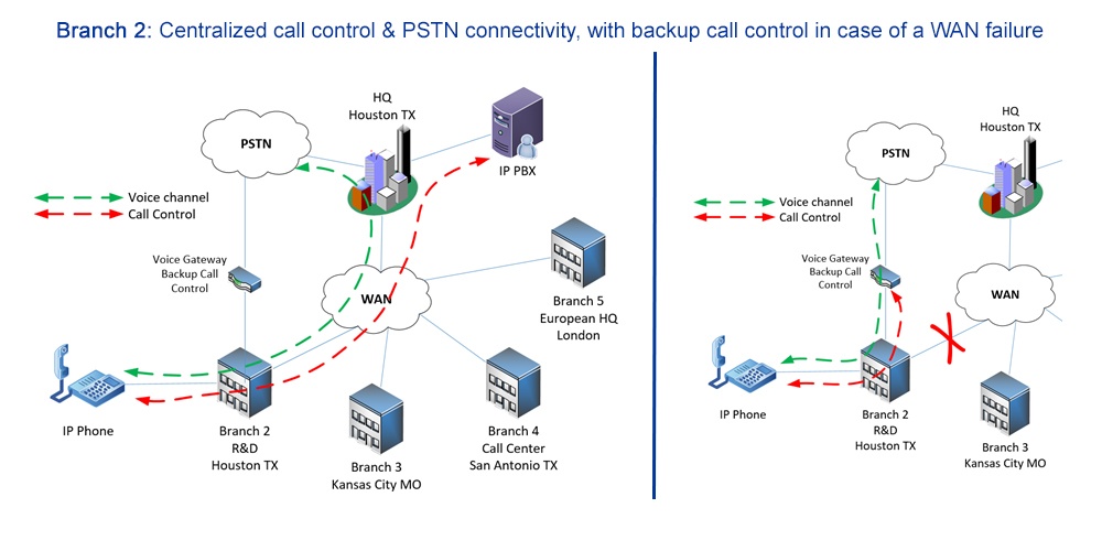 Branch 2 summary:
- Centralized call control and PSTN connectivity
- Backup call control and PSTN connectivity for a limited number of users in the event of a WAN failure
Branch 3
While telephony may not be mission critical for this site, the correct caller ID and the use of local area codes for customers in Missouri to reach this branch are essential. For this reason, a distributed PSTN solution is necessary; a local PSTN connection with a local area code must be established. However, centralized call control over the WAN can still be maintained. Therefore, redundancy is only necessary for call control and can be provided for any number of users, from a small subset to the whole branch. The following diagram depicts this branch under normal circumstances (left) and during a WAN failure (right).
Since PSTN calls always use the local PSTN connection, local backup only needs to be provided for call control.
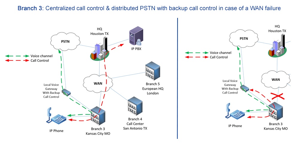
Branch 3 summary:
- Centralized call control
- Distributed PSTN connectivity
- Continues to function during a WAN failure
- Provides correct caller ID and avoids long distance charges for local calls
- Redundancy for call control for any number of users in the event of a WAN failure
Branch 4
Branch 4 houses a call center, so telephony is mission critical for all employees. A good solution for this site is a distributed call control implementation with distributed PSTN connectivity so that a WAN failure will have no effect on the call center. No redundancy needs be implemented here, since the design itself does not depend on the WAN. If a WAN failure occurs, only internal short code calling between Branch 4 and other company locations would be affected.
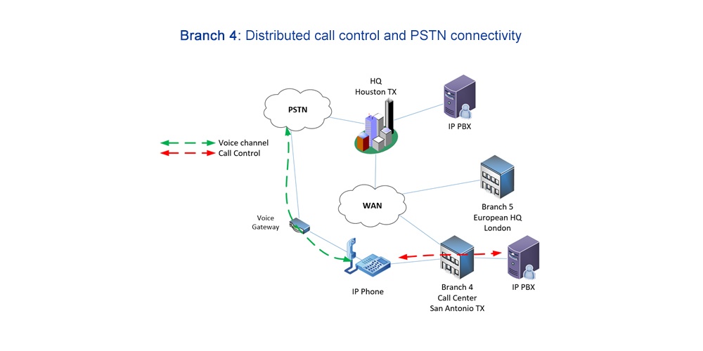
Branch 4 summary:
- Distributed call control
- Distributed PSTN connectivity
- Continues to function during a WAN failure
- Provides correct caller ID and avoids long distance charges for local calls
- No backup necessary; redundancy is built into the design
- This is a more costly solution
Branch 5
Because Branch 5 is in a different country, distributed PSTN is essential. Without it, local calls from Branch 5 in London would be charged as long distance calls, as if they were made from HQ, and caller IDs would be incorrect. Although centralized call control can be implemented, due to the long physical distances and the latency involved, a distributed call control implementation is strongly recommended. For all intents and purposes, Branch 5 has the same characteristics as Branch 4 except for one important advantage: because it is in a different country, it provides an opportunity to achieve significant cost savings using Tail End Hop Off (TEHO), a technique that is illustrated in the following diagram, which shows a call being made from HQ to a customer in London.
You can read more about TEHO in this article about dial plan normalization for multisite VoIP deployments.
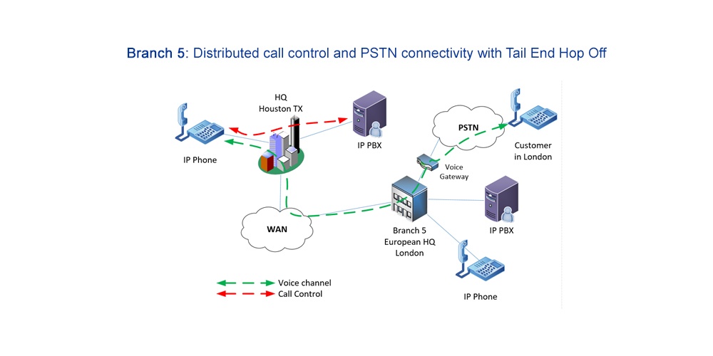
Branch 5 summary:
- Distributed call control
- Distributed PSTN connectivity
- Continues to function during a WAN failure
- Displays correct caller ID and avoids long distance charges for local calls
- No backup necessary; redundancy is built into the design
- Provides cost-savings opportunity through TEHO
Conclusion
In this case study, we have shown how a single multisite organization can have a variety of communication needs for its different locations. The variety can be so extensive that each site may require a different architecture, resulting in a hybrid telephony solution. VoIP and its related technologies have the versatility, the capacity and the rich feature sets necessary to satisfy even the most demanding and specialized telephony requirements.
You may also like:
How and when to deploy distributed call processing in a multisite environment
How to set up centralized call processing in a multisite enterprise
Tips for streamlining dial plan normalization in multisite VoIP deployments


Comments